|
This page discusses basic electric
guitar wiring and alternative ideas. Wiring is shown as wiring diagrams
rather than schematics for the benefit of the novice. Attempts are
made to explain concepts in plain English.
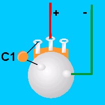
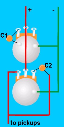
The Tone Control A basic tone control consists of a capacitor and a potentiometer (the tone control itself). The illustration below if the basic wiring for a tone control. The view is as you would see it from the bottom of the potentiometer, wired for a right-handed guitar. The oval "blobs" on the potentiometer casing are solder connections. The ground wire should be soldered to the potentiometer casing for this tone control to work - and it helps shield out unwanted noise (really noticeable if not done this way and you use metal knobs). The components used are as follows: Another Tone Control Since treble frequencies pass through a capacitor, what would happen if you routed the positive lead THROUGH the capacitor rather than having it ground out frequencies? The answer: just the opposite - the signal from you pickups would pass through the capacitor and only treble frequencies would get through. Aha! A new type of tone control. The illustration below shows this type of wiring in a bit of an advanced concept. A NEW IDEA: What would happen if we used a potentiometer
similar to that found in home stereo balance controls (with a center stopping
position and controlling two channels at once)? We could use the
center position as an "Off" position for the tone control, and use each
direction of rotation as different types of tone controls.
The components used are as follows: Again, the positive (+) and ground (-) leads can be wired from the output
jack. The positive lead labeled "to pickups" should go to the next
control in the normal flow of the signal (usually a volume control).
Treble Saver Volume Control Turning down your volume control typically reduces treble at the same time, resulting in a duller tone. Here is a way to retain the treble when you turn down your volume. 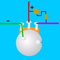
The objects connected to the red and purple wires are a capacitor and resistor in series. The round brown object is a capacitor, typically around .001 microfarads. The rectangular brown object is a resistor, typically around 150K ohms. Increasing the value of the capacitor will expand the treble range you're preserving. Too large a value, end you'll be preserving midrange, too. Too small a value and you'll only be preserving the highest treble frequencies. The value of the resistor determines the volume of the preserved treble. Too small a value and your guitar will get brighter when you turn down the volume. Too large a value and you won't be preserving much treble at all. Craig's Tip: I use a trim potentiometer instead of a resistor, typically 200K ohm. This lets me tailor the resistor to match the guitar's volume control and pickups to achieve the maximum benefit.
|